





16
2026-01
What are the advantages of Surge Arrester?
Surge arrester is a key component used in power systems and electrical equipment to limit overvoltage and protect the insulation of equipment. Its core advantages revolve around...


21 Years
Sarah Electric - A Trusted China Factory Since 2005
Yueqing Sarah Electric Co., Ltd. is located in Wengyang Industrial, Yueqing, Wenzhou, China. It covers an area of about 35,000 square meters and currently employs about 100 people. The company was established in June 2005, and so far, Sarah's products, including transformers, surge arresters, insulators, etc., have been exported all over the world.
Yueqing Sarah Electric Co., Ltd. exports goods to many countries, including Sweden, Finland, England, Norway, Spain, Argentina, Venezuela, Chile, Peru, Colombia, Brazil, America, Mexico, South Africa, Zambia, Zimbabwe, Kenya, Australia, the Philippines, Vietnam, Indonesia, Korea, India, Malaysia, Yemen, Iran, and so on, and we have lots of agencies, like in Sweden, Argentina, South Africa, Australia, Vietnam, and so on.
View More

Sarah Electric operates as a manufacturing facility with fully optimized production lines and stable supply capabilities. We offer a diverse range of electrical transformers—including both dry-type and oil-immersed models—spanning various voltage classes. These solutions are designed to adapt to a wide spectrum of engineering scenarios, facilitating efficient power transmission and distribution for both residential and industrial applications.
Transformers feature a robust internal structure and utilize electromagnetic induction to facilitate voltage conversion during operation.
Their basic construction consists of a closed iron core and high- and low-voltage coils wound around it. When an alternating current is applied to the high-voltage side, an alternating magnetic field is generated within the iron core. As this magnetic field traverses the low-voltage side, it induces a new alternating voltage within the low-voltage coils.
By adjusting the ratio of turns between the input and output coils, the transformer can precisely step down the voltage, thereby meeting specific project requirements.
Characteristics: Installed at the end of distribution lines; capable of long-term continuous operation; capacities typically range from 25 kVA to 5,000 kVA.
Function: Converts medium-voltage power into low-voltage power.
Common Applications: Residential buildings, commercial buildings, rural power grids, industrial parks, etc.
Characteristics: Large capacity; high operational efficiency; suitable for high-voltage or ultra-high-voltage systems.
Function: Responsible for stepping up or stepping down high-voltage power.
Common Applications: Power generation plants, power transmission grids, and large-scale substations.
Characteristics: Utilizes insulating oil for cooling and insulation; features strong heat dissipation capabilities, excellent overload capacity, and stable operation.
Common Applications: Power distribution systems, industrial manufacturing facilities, new energy power stations, and outdoor installation environments.
Characteristics: Does not use insulating oil; relies on air or epoxy resin for insulation and heat dissipation; offers excellent fire resistance, safety, and environmental friendliness.
Common Applications: Areas with high pedestrian traffic, hospitals, schools, and other critical zones.
Characteristics: Installed on utility poles; requires minimal ground space; involves low initial investment costs.
Common Applications: Rural and suburban power distribution systems.
Characteristics: Features a fully enclosed cabinet design; installed on a ground-level concrete pad; offers high safety, superior protection against external elements, and low noise levels.
Common Applications: Commercial districts and residential communities within urban areas.
Characteristics: Reduces electrical interference through electrical isolation; features complete separation between input and output circuits.
Function: Enhances equipment safety and improves power quality.
Common Applications: Medical equipment, automation control systems, precision instruments, and communication devices.
Characteristics: Capable of ultra-high current output; possesses strong short-circuit withstand capability and high resistance to impact loads.
Function: Supplies power to high-energy-consumption equipment, such as electric arc furnaces and smelting furnaces.
Common Applications: Steel mills, the metallurgical industry, and non-ferrous metal processing facilities.
|
Type |
Voltage Level |
Installation Environment |
Main Applications |
|
Medium/Low Voltage |
Indoor / Outdoor |
Power Distribution Systems |
|
|
High/Extra-High Voltage |
Substation |
Power Transmission Systems |
|
|
Multiple Voltage Levels |
Primarily Outdoor |
Industry and Power Grids |
|
|
Medium/Low Voltage |
Indoor |
Commercial Buildings |
|
|
Medium/Low Voltage |
Outdoor |
Rural Power Distribution |
|
|
Medium/Low Voltage |
Outdoor |
Urban Power Distribution |
|
|
Isolation Transformer |
Low Voltage |
Indoor |
Equipment Protection |
|
Furnace Transformer |
Special High Current |
Industrial Site |
Smelting Industry |
Because the proper functioning of power systems relies entirely on transformers; from power plants to end-users, virtually every kilowatt-hour of electricity must pass through a transformer.
High-efficiency transformers not only facilitate voltage conversion but also help users to:
● Enhance power transmission efficiency
● Minimize energy loss
● Safeguard equipment safety
● Improve power supply stability
● Reduce long-term operating costs
The voltage on the high-voltage side of a transformer depends on the local power grid structure; it must precisely match the transmission voltage of the public grid or the upstream substation serving the project site.
Please refer to the following voltage guidelines—based on your specific country, region, and project requirements—or consult Sarah Electric directly:
11 kV: United Kingdom, Southeast Asia, Africa, Australia, India, and other regions utilizing Commonwealth-based electrical systems.
33 kV / 35 kV: Commonly used in large-scale industrial parks, medium-sized substations, or new energy power collection systems.
10 kV / 20 kV: Mainland China and certain European countries.
13.8 kV / 4.16 kV: Widely used in North America (US standards) and parts of South America.
The voltage on the low-voltage side of a transformer depends on the end-use load equipment; it must match the rated operating voltage of the factory production lines, commercial buildings, or residential power grids it serves.
Industrial Three-Phase Power: Used to drive heavy machinery, electric motors, variable frequency drives (VFDs), etc.
If the project is located in a region that adopts International Electrotechnical Commission (IEC) standards, 400 V (or 415 V under older standards) is typically selected.
If the project is located in North America (US standards), 480 V or 208 V may be required.
Residential / Single-Phase Power: Used for lighting, office equipment, and standard household appliances.
Common choices include 220 V, 230 V, or 240 V.
Need to start a new project? Provide the following information immediately, and Sarah Electric will respond to you promptly:
✓ Primary Voltage
✓ Secondary Voltage
✓ Required Capacity (kVA)
✓ Frequency (50Hz or 60Hz)
✓ Installation Environment (Indoor or Outdoor)
✓ Altitude
✓ Project Location (Country)

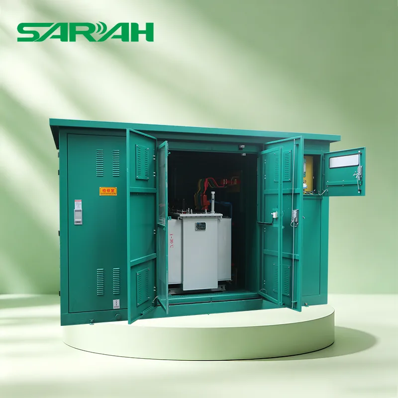
Looking for a reliable manufacturer and supplier of box type substations? Sarah Electric offers customized solutions featuring a factory-prefabricated, modular, and fully enclosed outdoor design. The equipment is corrosion-resistant, moisture-proof, and theft-resistant, making it ideal for urban distribution networks, industrial applications, the new energy sector, and temporary power supply needs.
Taking a typical 10kV/0.4kV box-type substation as an example, the workflow can be summarized as follows: Medium-voltage grid (10kV) → High-voltage switchgear → Distribution transformer → Low-voltage switchgear → User equipment (400V).
The box-type substation first connects to the power grid via a high-voltage incoming line. The high-voltage side is primarily responsible for receiving electrical energy from the grid, controlling the power supply (switching on/off), and protecting the transformer.
After entering the substation, the high-voltage electricity first passes through the high-voltage switchgear.
Under normal conditions, the switchgear controls the flow of electricity into the transformer. In the event of a fault, protection devices detect the abnormality and trigger the switchgear to interrupt the fault current, thereby protecting the transformer and lines and preventing the fault from escalating.
This is the core stage of the substation's overall operation; the transformer achieves voltage transformation based on the principle of electromagnetic induction.
High-voltage electricity enters the transformer's high-voltage winding, the iron core transfers magnetic energy, and the low-voltage winding outputs low-voltage electricity. Voltage reduction is achieved through the design of the windings and the adjustment of the turns ratio.
Electricity stepped down by the transformer enters the low-voltage cabinet. The low-voltage switchgear is responsible for distributing power, controlling loads, and providing overload protection.
Finally, the electricity is distributed and supplied to applications such as factory equipment, building lighting, motor systems, and charging equipment.
The box-type substation consists of three independent compartments:
Responsible for receiving 10kV or 35kV high-voltage incoming power. It houses HV load switches, circuit breakers, fuses, surge arresters, and protection and metering devices to facilitate power input, control, and protection.
Steps down high voltage (e.g., 10kV/35kV) to low voltage (e.g., 0.4kV).
Transformer options include oil-immersed (S13/S22) or dry-type (SCB) units; capacity generally does not exceed 1600kVA (typically ≤1250kVA for civil applications).
Responsible for power distribution. It houses the LV main switch, outgoing circuits, reactive power compensation (capacitor cabinets), energy metering, and intelligent monitoring equipment.
Constructed from Al-Zn coated steel sheets or composite panels, offering resistance to moisture, rust, dust, rodents, fire, and theft, as well as thermal insulation properties.
Protection ratings range from IP23 to IP44; customization is available, and the unit operates reliably in ambient temperatures from -40°C to +40°C.
1. Urban public distribution networks: Residential complexes, commercial pedestrian streets, underground parking garages, and lighting for urban roads and tunnels.
2. New energy power generation: Centralized photovoltaic (PV) power plants and onshore/offshore wind farms (serving as step-up and grid-connection nodes).
3. Industry and infrastructure: Mining areas, petrochemical zones, EV super-charging hubs, and data centers.
4. Temporary and emergency power supply: Temporary power for construction sites and rapid, mobile power delivery for post-disaster emergency response.
|
Comparison Criteria |
Box-type Substation |
Traditional Substation |
|
Structure |
Integrated enclosure |
Distributed equipment installation |
|
Installation Method |
Prefabricated |
On-site construction |
|
Footprint |
Compact |
Large scale |
|
Construction Period |
Short (dimensions) |
Long duration |
|
Transportation |
Shipped as a complete unit |
Transport of individual equipment components |
|
On-site Construction |
Minimal |
High number of components |
|
Scalability |
Standard |
High requirements |
|
Initial Investment |
Relatively low |
High complexity |
|
Application Scenarios |
Small to medium-scale substation requirements |
Large-scale power grid projects |
In accordance with project contract requirements, Sarah Electric can dispatch senior electrical engineers to overseas project sites to supervise the installation and testing of box-type substations.
We assist clients in performing circuit resistance tests, withstand voltage tests (Hi-Pot tests), SF6 gas tightness checks, and setting verification for microprocessor-based protection relays.
Leveraging over 20 years of experience, Sarah Electric has established a dedicated technical support team capable of providing rapid responses and preliminary troubleshooting plans within 24 hours.
We offer remote guidance via video link to assist on-site O&M personnel with equipment inspections and troubleshooting.
We provide training for overseas power utilities and local engineering teams covering the following areas:
● Safe equipment operating procedures (prevention of misoperation and "Five-Prevention" interlocking systems).
● Preventive Maintenance (PM) checklists.
● Partial Discharge (PD) monitoring and infrared thermography inspection methods.
A: Our enclosures feature customized, heavy-duty anti-corrosion and protective designs tailored for extreme environments:
1. Material Selection: Options include hot-dip galvanized steel, Al-Zn alloy sheets, stainless steel (304/316L), or GFRC composite cement panels.
2. Anti-corrosion Coating: Surfaces are finished with heavy-duty powder coating to resist coastal salt spray corrosion.
3. Environmental Control: Equipped with automatic temperature/humidity controllers and heater/dehumidifiers; combined with sandwich insulation panels, these prevent freezing in cold regions and condensation-induced short circuits in high-humidity areas.
A: It depends on the installation environment's fire safety requirements and your budget:
1. Dry-type Transformer: Flame-retardant, self-extinguishing, and poses no risk of oil contamination. Suitable for installation near populated areas (commercial centers, high-rises), in basements, or in locations with strict fire safety requirements.
2. Oil-immersed Transformer: Offers excellent heat dissipation, strong overload capacity, and high cost-effectiveness, with relatively low maintenance costs. Suitable for outdoor public distribution networks, industrial parks, and remote photovoltaic or wind farms.
A:
European-style: Features separate compartments for high/low-voltage switchgear and the transformer; offers flexible configuration, comprehensive protection, and easy maintenance, but has a larger footprint. Suitable for urban residential areas and industrial/mining enterprises.
American-style: High-voltage switchgear and the transformer share a common oil tank; compact size (approx. 1/3 of the European style), lower cost, and fully sealed/maintenance-free, though maintenance access is more difficult and protection features are simpler. Suitable for coastal areas, wind farms, and locations with limited space.

Switchgear is one of the product lines offered by Sarah Electric, covering both high-voltage and low-voltage applications. Within our electrical equipment solutions, this product range controls the switching of circuits and rapidly interrupts abnormal currents during faults, thereby protecting transformers, cables, power generation equipment, and electrical loads.
To meet operational and maintenance needs, switchgear can connect or disconnect specific high- and low-voltage lines at any time—for example, cutting off power to a specific area during maintenance-related outages.
In the event of a lightning strike, short circuit, or severe overload, the internal intelligent protection devices instantly trigger the circuit breaker to trip, isolating the faulty section and protecting valuable downstream assets such as transformers and motors.
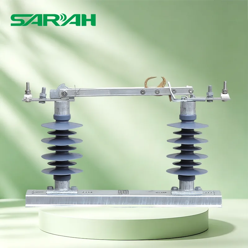
It provides a visible or highly reliable physical disconnection point, ensuring that high-voltage power is not accidentally energized while maintenance personnel are working underground or on utility poles.
Function: Normally makes and breaks load current; interrupts short-circuit current.
Common types: Vacuum Circuit Breaker, SF₆ Circuit Breaker, Air Circuit Breaker.
Function: Provides a visible break point for isolation during maintenance.
Characteristic: Cannot interrupt high fault currents.
Function: Collects and distributes electrical energy; serves as the primary current-carrying component within the switchgear.
Function: Detects abnormal current, abnormal voltage, and ground faults, and sends trip signals to the circuit breaker.
CT (Current Transformer): Used for measuring current and providing protection signals.
PT (Potential Transformer): Used for measuring voltage and providing voltage protection.
|
Type |
Voltage range |
Typical Applications |
|
Low-voltage switchgear |
≤ 1 kV (typically 380 V/400 V) |
Power distribution for factories, buildings, and residential areas |
|
Medium-voltage switchgear |
1 kV – 52 kV (commonly 10 kV/20 kV/35 kV) |
Urban distribution networks; industrial and commercial power distribution |
|
High-voltage switchgear |
52 kV – 245 kV |
Substations and transmission lines |
|
Extra-high-voltage switchgear |
> 245 kV |
Ultra-high voltage (UHV) transmission; power plant step-up substations |
Indoor type: Installed in power distribution or switchgear rooms; lower ingress protection requirements.
Outdoor type: Installed outdoors; requires resistance to water, dust, and corrosion.
Air-insulated switchgear (AIS): Uses air as the insulation medium; larger footprint; mature technology.
SF₆ gas-insulated switchgear (GIS): Uses SF₆ gas for insulation and arc quenching; compact size; suitable for space-constrained locations.
Solid-insulated switchgear: Uses solid insulation materials such as epoxy resin; maintenance-free.
|
Equipment |
Positioning |
Key Differences |
|
Switchgear |
Control + Protection + Isolation |
Incorporates comprehensive functions such as circuit breakers, disconnect switches, and protection |
|
Transformer |
Voltage transformation |
Steps voltage levels up or down; lacks circuit-breaking or protection capabilities |
|
Ring Main Unit (RMU) |
Simplified switchgear |
A type of switchgear that typically uses load-break switches and fuses instead of circuit breakers |
|
Transformer + simplified switch |
Centered on the transformer; the high-voltage side is equipped only with fuses and load-break switches |
|
|
MCC / Distribution Panel |
Low-voltage power distribution |
Motor control and power distribution equipment for the low-voltage side |
1. Operators must wear appropriate personal protective equipment (PPE)—including insulating gloves, insulating boots, a hard hat, and safety goggles—when performing any operations on the switchgear.
2. When operating high-voltage equipment, a voltage detector rated for the appropriate voltage level must be used to verify the absence of voltage.
3. Before maintenance, the four-step safety procedure must be executed: Power Off → Verify Voltage → Ground → Place Warning Signs.
4. Entering the high-voltage switchgear room alone is strictly prohibited.
5. After opening a cabinet door, verify that the equipment is de-energized and grounded before entering.
1. Protection settings must not be altered arbitrarily; any modifications require technical approval.
2. Disconnectors and earthing switches in spare bays must be kept in the correct position and locked.
3. No tools or debris may be left inside the cabinet.
4. Power must not be applied until the cable compartment door is closed.
5. Prevent small animals from entering the cabinet; sealing cable entry points and installing anti-rodent barriers is recommended.
1. Fire inside the cabinet: Immediately disconnect the upstream power supply; use a CO₂ or dry powder fire extinguisher; the use of water is strictly prohibited.
2. SF₆ gas leakage: Personnel must evacuate immediately and ventilate the area; entry for remediation is permitted only while wearing a gas mask.
3. Circuit breaker failure to operate: Do not force repeated closing attempts; investigate and resolve the cause before proceeding.
4. Busbar short-circuit trip: Locate the fault point, clear the fault, and then attempt to restore power section by section.
A:
Power-off sequence: First, open the circuit breaker (interrupt current) → then open the load-side disconnector → finally, open the power-side disconnector.
Power-on sequence: First, close the power-side disconnector → then close the load-side disconnector → finally, close the circuit breaker.
Golden Rule: Disconnectors must never be operated under load.
A: Please provide the following to Sarah Electric:
System parameters: Rated voltage, maximum operating voltage, rated frequency.
Current parameters: Rated current for main and branch busbars, rated short-time withstand current (e.g., 25kA/4s), rated peak withstand current.
Environmental conditions: Installation location (indoor/outdoor), maximum/minimum ambient temperature, altitude, pollution level.
Configuration details: Primary circuit diagram (single-line diagram), secondary control schematic, protection configuration requirements.
A: Yes. Our switchgear's secondary control compartment comes standard with microprocessor-based integrated protection relays, supporting mainstream international power communication protocols such as IEC 61850, Modbus-RTU/TCP, and DNP3.0.
Combined with built-in high-precision CT/VT instrument transformers and motorized operating mechanisms, the system can directly transmit current, voltage, switch status, and fault alarms to the main control room or cloud-based SCADA systems, enabling remote telemetry, remote signaling, and remote control.

Sarah Electric is a manufacturer and supplier of surge arresters based in China. Our products protect transformers and other expensive power equipment from damage caused by overvoltage; they are capable of responding rapidly when hazardous voltages occur, thereby minimizing the risk of equipment damage and ensuring the stable operation of power supply systems.
When a power grid is struck by lightning or experiences internal switching overvoltages, ultra-high voltage pulses—reaching levels several or even tens of times greater than the normal operating voltage—are instantaneously generated within the grid; protective equipment is required to intercept these surges.
Without protection, these high-voltage surge waves would instantly puncture the coil insulation of transformers, leading to equipment burnout or even explosion.
A surge arrester reacts within a few microseconds to safely divert these massive, destructive currents into the earth.
Once the overvoltage subsides and the power grid returns to its normal operating voltage, the surge arrester immediately reverts to a high-impedance state, thereby ensuring that normal power transmission remains unaffected.
When lightning directly strikes transmission lines—or when atmospheric discharges induce massive currents within the lines—it generates instantaneous high-voltage surge waves reaching tens or even hundreds of thousands of volts.
Our Solution: Surge arresters react within nanoseconds, rapidly switching to a conductive state to safely divert lightning currents into the ground.
During grid operations—such as the disconnection of heavy loads or the switching off of unloaded transformers—the energy exchange between inductive and capacitive components can induce internal switching overvoltages within the system.
Our Solution: Surge arresters possess exceptional nonlinear energy-absorbing capabilities, effectively flattening voltage transients caused by these internal switching operations and stabilizing the system voltage.
If a transformer or other critical high-voltage equipment is damaged by a surge-induced breakdown, it often leads to widespread, prolonged power outages.
Our Solution: By safely diverting surge currents, our devices ensure the continuous operation of the entire power distribution network, thereby minimizing the risk of power outages.
In regions prone to severe thunderstorms (such as the rainy-season zones of Southeast Asia or mining areas in Africa)—or in areas with highly volatile power grids—standard power equipment is highly susceptible to frequent insulation flashovers or short-circuit faults.
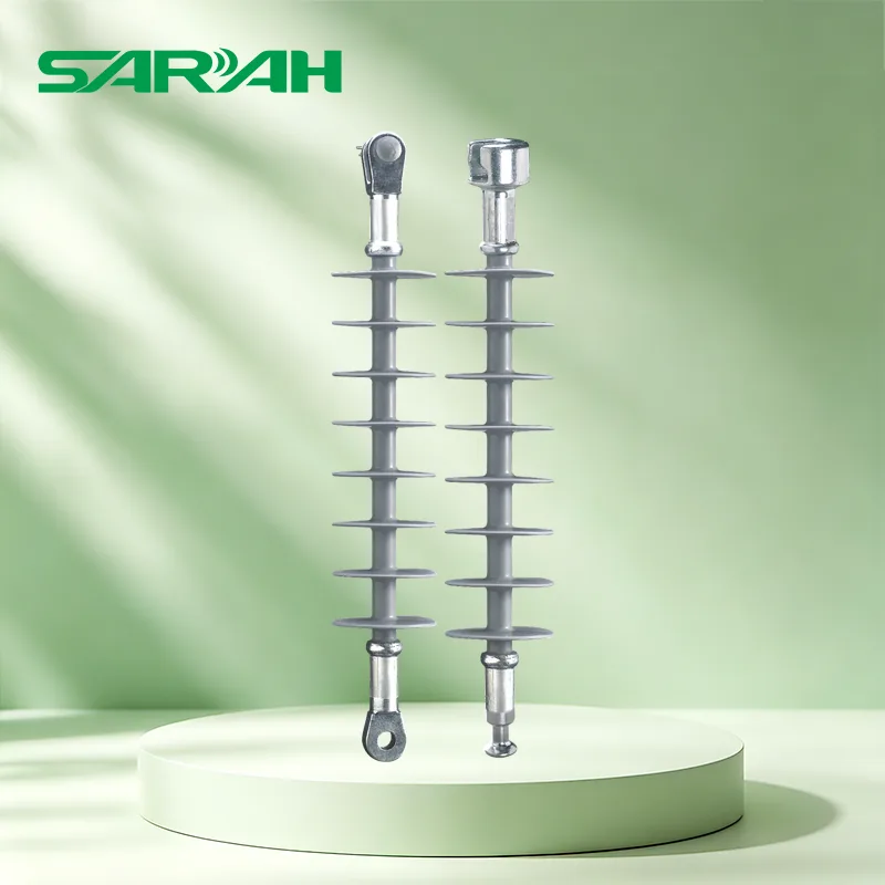
Our Solution: Surge arresters manufactured by Sarah Electric feature high-quality composite insulation housings, offering superior resistance to contamination, moisture, and explosion hazards.
|
Type |
Structural Features |
Core Advantages |
Limitations |
Typical Application Scenarios |
|
Silicone Rubber Composite Housing |
Lightweight; resistant to pollution flashover; impact-resistant; excellent explosion-proof performance |
Cost is slightly higher than that of traditional porcelain housings |
Power Distribution Systems, PV Power Stations, Coastal and High-Pollution Areas |
|
|
Porcelain Housing |
High mechanical strength; widely applied in traditional settings |
Heavier weight; moderate impact resistance |
Traditional Power Grids, Conventional Substations |
|
|
Medium-to-Low Voltage Distribution Protection Type |
Low cost; easy to install |
Discharge capacity is lower than that of substation-grade units |
Distribution Lines, Distribution Transformers, Industrial Power Supply |
|
|
Station Class Surge Arrester |
High Voltage Substation Protection Type |
Strong discharge capacity; high protection level |
Higher price and larger physical dimensions |
High-Voltage Substations, National Power Grids |
|
Gapless Surge Arrester |
Gapless Design |
Fast response speed; more stable protection; low maintenance requirements |
Demanding requirements for manufacturing processes |
Modern Distribution Systems, New Energy Projects |
|
Gapped Surge Arrester |
Gapped Structure |
Established technology; still utilized in certain specialized scenarios |
Slower response speed; requires more frequent maintenance |
Aging Power Systems |
|
Metal Oxide Surge Arrester |
Zinc Oxide (ZnO) Varistors |
Excellent non-linear characteristics; strong energy absorption capacity; long service life |
Higher cost compared to older-generation products |
Modern Power Grids, Industrial Distribution Systems |
|
Silicon Carbide Arrester |
Silicon Carbide Material |
Mature technology for traditional applications |
Performance is outdated and being gradually phased out |
Renovation of Aging Facilities |
A: If you prioritize lightweight design, ease of installation, and explosion-proof safety, we strongly recommend composite-insulated surge arresters.
If your application involves traditional infrastructure and you require an exceptionally long service life, porcelain-insulated surge arresters remain the classic choice.
We manufacture both types of products and can provide tailored selection recommendations based on the specific environmental conditions of your project.
A: Yes. Our products are impervious to heavy rain, high-salinity fog, and extreme cold; their fully sealed design ensures that the internal zinc oxide varistors remain protected from moisture.
A: Absolutely. PV power stations and wind power systems are typically installed outdoors, making them susceptible to lightning strikes and voltage fluctuations; therefore, they require high-performance surge arresters to ensure protection.
Discover our transformers, surge arresters, fuse cutouts, etc. Hot sale items with proven field performance, available for bulk order directly from Sarah Electric.

Address
No.101-103, Fu Hua Road, Leshang Chuangye Yuan, Wengyang Industrial Zone, Yueqing, Wenzhou, Zhejiang, China
Request a quote from Sarah Electric’s professional team—enjoy factory-direct prices, tailored OEM solutions, and responsive support for any project scale.
Stay informed about Sarah Electric’s global trade show schedule, new product launches, and industry updates.
16
2026-01
Surge arrester is a key component used in power systems and electrical equipment to limit overvoltage and protect the insulation of equipment. Its core advantages revolve around...

16
2026-01
Switchgear is a complete electrical device that integrates switchgear, measuring instruments, protective appliances, and auxiliary equipment. It is mainly used in the power system's...

16
2026-01
The box-type substation is a compact type of complete equipment that combines high-voltage switchgear, distribution transformers, and low-voltage distribution devices according to...

16
2026-01
Stationary non-rotating components: There is no mechanical movement. Energy is transmitted solely through electromagnetic induction. They operate reliably, are simple to maintain...

14
2026-09
A 20KV Power Transformer plays a critical role in medium-voltage power distribution, industrial facilities, commercial buildings, renewable energy projects, and utility networks. The right transformer must do more than convert voltage. It must provide stable operation, manageable losses, dependable insulation performance, appropriate thermal capacity, and long service life under real operating conditions.

07
2026-09
A 145KV power transformer is a critical component in high-voltage transmission and substation systems, helping utilities and industrial facilities transform electrical energy efficiently and safely. This guide explains its operating principles, major components, technical considerations, installation requirements, maintenance practices, common challenges, and practical selection factors.

31
2026-08
A 110KV Power Transformer 20000KVA is a critical electrical device designed for high-voltage power transmission and distribution systems. With its ability to step voltage levels up or down efficiently, this transformer plays an essential role in industrial facilities, substations, renewable energy projects, and urban power networks. This article explains the structure, working principles, applications, benefits, selection considerations, and maintenance methods of a 110KV 20000KVA power transformer while addressing common challenges faced by power system operators and engineering buyers.

24
2026-08
A 33KV oil immersed distribution transformer is a critical component in medium- and high-voltage power distribution systems, helping reduce transmission voltage to a safer and more usable level for industrial facilities, commercial buildings, infrastructure projects, and utility networks. Selecting the right transformer involves much more than checking voltage and capacity.
20
2026-08
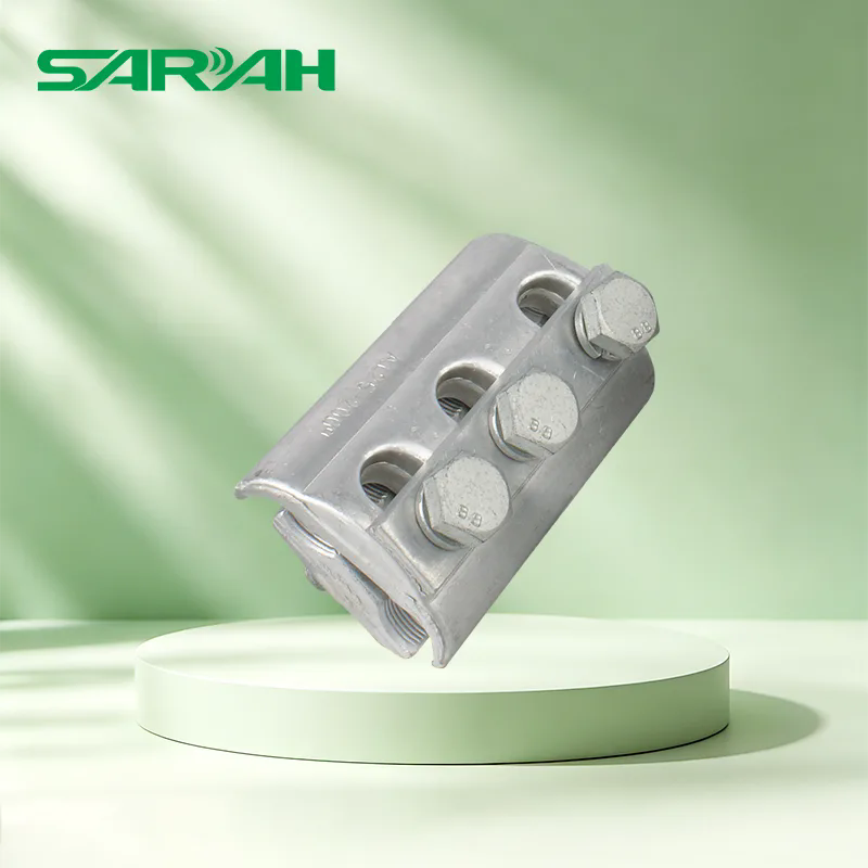
Discover what overhead line fittings are used for in power transmission systems. Learn about their functions, types, technical specifications, and reliability in harsh environments.

17
2026-08
A Pad Mounted Transformer is an essential component in underground electrical distribution networks, providing safe, reliable, and efficient voltage transformation for residential communities, commercial facilities, industrial projects, and renewable energy applications.
10
2026-08
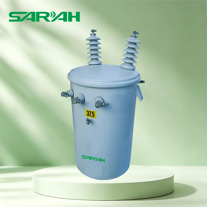
Pole Mounted Transformer plays a critical role in modern electrical distribution systems by safely reducing medium voltage electricity into usable low voltage power for residential, commercial, and industrial applications. This article explains how pole mounted transformers work, why they are widely adopted, what problems they solve, how to select the right transformer, and how reliable manufacturers help customers achieve safer and more efficient power management.

03
2026-08
Oil immersed transformer plays a critical role in modern electrical power systems by ensuring stable voltage conversion, efficient energy transmission, and long-term operational reliability. This article explains how oil immersed transformers work, their key advantages, applications, maintenance requirements, and how businesses can choose the right transformer solution to overcome common power distribution challenges.